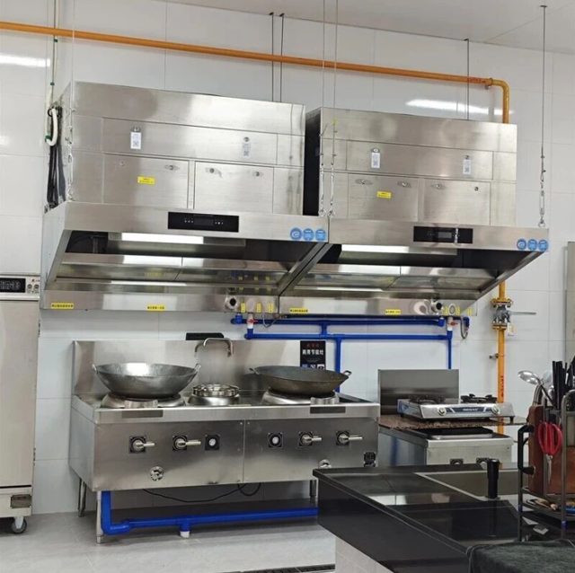
The exhaust system is usually the largest single air mover in a restaurant building, and in many kitchens it runs at full speed from the first breakfast prep cycle to the last dish pit shutdown. Yet when operators are asked what that system costs to run, the answer is almost always a guess. A structured energy audit turns that guess into a measured baseline — and the baseline is what separates a retrofit that pays back from one that merely looks efficient on a datasheet.
Why Kitchen Exhaust Energy Hides in Plain Sight
Energy managers routinely meter lighting, refrigeration, and HVAC plant, but the kitchen exhaust fan is often wired into a general distribution board with no sub-metering, no run-hour counter, and no record of actual airflow. The result is a load that can represent a substantial share of a restaurant’s total electricity use — and an even larger share of its heating and cooling cost through conditioned make-up air — while remaining invisible on every report the operator sees.
Two distinct energy streams need to be separated before any savings claim makes sense. The first is fan electricity: the brake kilowatts drawn by the exhaust fan and any associated supply fan, every hour they run. The second is conditioned-air loss: every cubic metre of air the hood exhausts must be replaced by make-up air that has to be heated, cooled, or dehumidified to room conditions. In extreme climates the second stream can cost more than the first, which is why a nameplate-reading exercise alone never produces a credible baseline.
There is also a commercial reason the audit comes first. Equipment suppliers, ESCOs, and utility rebate programmes all price their offers against a claimed saving. Without a measured baseline, the operator has no way to test whether a promised thirty per cent reduction is real, or whether the savings calculation quietly assumed operating hours the kitchen never actually runs.
What a Baseline Audit Actually Measures
A defensible baseline rests on four measured quantities, gathered over a representative period rather than a single afternoon:
1. True electrical demand. Nameplate motor power is not consumption. A 7.5 kW motor coupled to a fan running against a throttled system curve may draw 5.2 kW; the same motor on an over-ventilated clean duct may draw more. A clamp-on power logger or a temporary kWh meter on the exhaust circuit, recording at one- to fifteen-minute intervals, captures the real load profile including the morning ramp, the lunch peak, the afternoon lull, and the evening surge.
2. Actual airflow. Duct airflow determines both fan energy (through the system curve) and conditioned-air loss. A pitot-tube traverse or a calibrated thermal anemometer grid at a straight duct section gives volumetric flow in m³/h; hood face-velocity readings supplement this where duct access is limited. Measuring at multiple points in the day matters because many kitchens already run against partially closed dampers or degraded filters that shift the operating point.
3. Run hours and duty profile. The single most common audit surprise is the difference between assumed and actual operating hours. Kitchens frequently run exhaust at full speed through prep, service, and cleaning — twelve to sixteen hours — although full capture is only needed while cooking appliances are hot. A simple hour meter or the timestamped current trace from the power logger establishes the real duty cycle.
4. Make-up air conditions. Outdoor design temperature and humidity for the site, the indoor setpoint, and the efficiency of the heating and cooling plant convert each cubic metre of exhausted air into an energy cost. This is the step that turns airflow data into money, and it is climate-specific: the same 4,000 m³/h hood is a very different financial proposition in Riyadh, Singapore, or Munich.
A baseline shorter than two full trading weeks risks missing the weekly rhythm. Include at least one full weekend and any known peak event — a brunch service, a banquet night, a delivery surge — before treating the numbers as representative.
Field Measurement: Getting Fan Power and Airflow Right
Measurement quality decides whether the baseline survives scrutiny. For fan power, true-RMS logging is essential because variable-speed drives and soft starters distort current waveforms; a cheap average-responding clamp meter will misread a VFD-fed motor by enough to corrupt the whole audit. Where the fan shares a breaker with other loads, a panel-level logger with CTs on the correct phases is cleaner than trying to isolate the circuit downstream.
For airflow, the duct traverse remains the reference method: a grid of velocity readings across a straight section at least seven and a half duct diameters from the nearest elbow, averaged to a single figure. Kitchen grease ducts rarely offer textbook straight runs, so a practical compromise is a thermal anemometer array at the best available section, cross-checked against hood face velocity measured with a vane anemometer across the capture opening. The two methods should agree within roughly fifteen per cent; a wider gap usually indicates leakage, a blocked filter bank, or a measurement point too close to a disturbance.
Static pressure is the third leg. Tappings either side of the fan, the filtration stages, and the hood reveal where pressure drop is being generated — and therefore where energy is being wasted. A system that started life at 600 Pa of total resistance and now pulls 900 Pa is telling the auditor that grease-laden filters or a fouled electrostatic precipitator are quietly taxing the fan every hour it runs. That finding alone often justifies the audit: restoring clean filters can recover performance that no new equipment purchase would have delivered.
The Conditioned-Air Ledger
Translating airflow into thermal cost requires only basic psychrometrics, but it must be done honestly. The annual thermal burden of an exhaust stream is the airflow multiplied by run hours, multiplied by the average enthalpy difference between outdoor and indoor air, divided by the seasonal efficiency of the plant that treats the make-up air. In heating climates the number is dominated by winter design temperatures; in humid climates by latent load; in mild climates it may be small enough that fan electricity dominates instead.
Worked example, deliberately simplified: a 3,000 m³/h hood running twelve hours a day in a climate where make-up air must be heated through an average of 12 K for a third of the year. At roughly 0.34 Wh per m³ per kelvin, the heating burden alone approaches 4,900 kWh a year — before any cooling or dehumidification is counted, and before the fan’s own electricity. Auditors who skip this ledger routinely understate the value of any measure that reduces exhausted volume, whether that is demand-controlled ventilation, a better-capturing hood that allows a lower design airflow, or a recirculating architecture that exhausts nothing at all.
This is also where appliance scheduling shows up on the balance sheet. Combi ovens, fryers, and charbroilers do not all run at once for the whole trading day. If the baseline shows long periods where measured cooking load — appliance temperature, gas flow, or simply kitchen activity — is far below the exhaust system’s design assumption, the gap between them is the recoverable energy, and it is usually large.
Reading the Baseline: Fan Laws and Part-Load Reality
The fan affinity laws are the audit’s most powerful interpretive tool: power varies with the cube of fan speed. Cutting airflow by twenty per cent through speed reduction — not damper throttling — roughly halves fan power. A constant-speed fan throttled by dampers wastes this opportunity entirely, because the motor still does the work of moving air against an artificially created resistance. That is why the first question the baseline answers is not “what new fan do we need” but “is the existing fan ever allowed to slow down”.
Demand-controlled kitchen ventilation (DCKV) exploits exactly this physics. Temperature sensors in the hood, optical or particulate sensors over the cookline, or direct appliance-status signals modulate fan speed so the system tracks cooking load rather than the clock. Field studies and utility evaluations commonly report fan energy reductions in the thirty to sixty per cent range for variable-duty kitchens, with additional savings on the conditioned-air ledger whenever airflow drops below the design volume. The baseline data decides whether a given site sits at the high or low end of that range: a kitchen whose logger trace shows a flat full-load profile for fourteen hours has less to recover from modulation and more to recover from discipline and scheduling.
Motor and drive efficiency complete the picture. Older belt-driven fans lose several per cent of shaft power in the drive and more in worn belts; EC (electronically commutated) motors and modern VFD-fed premium-efficiency motors raise wire-to-air efficiency, particularly at the part-load conditions the affinity laws make so cheap. The audit should record motor nameplate efficiency class, drive type, and belt condition, because these inexpensive details often carry a better payback than any headline equipment change.
Standards, Verification, and the Compliance Boundary
Energy measures in kitchen exhaust operate inside a compliance frame that must be respected in the baseline study itself. ASHRAE 90.1 sets fan-power and demand-control expectations for commercial kitchens in many jurisdictions — including automatic speed reduction provisions above defined exhaust thresholds — while EN 16282 governs the design and hygiene of the ventilation equipment in European practice. NFPA 96 and its international equivalents impose the non-negotiable boundary: capture and containment of grease-laden vapour must be maintained whenever appliances operate, so any control strategy that reduces airflow must be proven to hold capture at every reduced state. An audit that proposes savings by simply turning fans down without a capture test is not an energy measure; it is a code violation waiting for an inspector.
For the financial side, the IPMVP (International Performance Measurement and Verification Protocol) provides the recognised structure: define the baseline period, measure the independent variables — trading hours, covers, weather — and commit to a post-retrofit measurement plan using the same instruments. Even a simple Option C whole-meter approach, or Option B sub-metering of the exhaust circuit, converts the retrofit from a promise into a verified saving, which is increasingly what insurers, landlords, and rebate programmes ask to see.
What Audits Commonly Find
Across real kitchens the same findings recur. Fans specified for a design condition the menu never reaches, running at full speed against throttled dampers. Filtration stages so loaded with grease that pressure drop has climbed fifty per cent above the commissioning value, silently inflating fan power. Exhaust systems started by habit an hour before the first appliance is lit and left running through breakdown and cleaning. Make-up air introduced untreated through open windows and transfer grilles, so the kitchen is simultaneously over-ventilated and uncomfortable — paying the thermal penalty without buying the capture performance.
Seasonal and event-driven operations add their own twist. A venue whose cookline runs flat out for weekend banquets but idles through weekday lunches has a duty profile that a single design airflow can never fit; the baseline makes that visible. Operators running market stalls, pop-up kitchens, or event catering face the extreme case — a cookline that exists only for the event — and for them self-contained mobile catering carts with integrated filtration are often the honest answer, because a fixed exhaust system sized for occasional load would spend most of its life moving air for nobody.
From Baseline to Design Response
Once the baseline is on the table, the design response follows from it rather than from a catalogue. Where the audit shows high exhausted volume against modest cooking load — the classic over-ventilated kitchen — the cheapest interventions are scheduling discipline, cleaning regimes that restore the original pressure drop, and speed control that tracks real demand. Where the conditioned-air ledger dominates and the building makes ducting expensive or impossible, a recirculating architecture changes the equation fundamentally: air is captured, purified, and returned to the room, so the thermal burden of make-up air largely disappears from the baseline model altogether.
That is the niche addressed by Souniny’s ductless range hood family: an all-in-one hood pairing a multi-stage electrostatic cell with a carbon odour stage, sized from the measured duty rather than a rule of thumb. The N-series covers light-fume cooklines — cafés, bakeries, breakfast operations — where the audit typically shows moderate airflow and long, steady hours; the ND-series serves heavy-fume lines such as fry stations and charcoal grills, where capture demand peaks hard and the affinity-law savings from matching airflow to load are largest. Pairing either with an Odor Removal Tower closes the loop on the gaseous phase so recirculation stays comfortable for staff and neighbours alike. Where the baseline instead confirms a genuine high-volume ducted requirement — a central production kitchen or a charcoal-heavy site with an existing shaft — the ducted ESP purifier range covers that end, and fan selection can be optimised against the measured system curve rather than a guessed one.
Whatever architecture the numbers point to, the audit discipline is the same: measure the load, reduce it where physics allows, verify the result with the same instruments, and file the baseline so the next refurbishment starts from evidence instead of assumption.